NNizwa نزوى
كتالوج المشاريع

سلطنة عُمان / نزوى / الإصدار 1.3

الأرض أولاً.
ثم المخطط العام.

المواصفات الفنية للمسح الجوي بالليدار والتصوير ثلاثي الأبعاد لموقع عجلة المشاهدة المقترحة.

خطوات المشغّل

للتسعير والتنسيق • اعتماد محيط العميل • تأكيد الضبط المساحي قبل الطيران

مقارنة حدود الموقع ومؤشر العجلة W
W · موقع مقترح، وليس نقطة توقيع

هدف المسح

تنفيذ مسح جوي بطائرة بدون طيار مزودة بمستشعر LiDAR وكاميرا RGB لإعداد المخطط العام لمشروع عجلة مشاهدة والتطوير المرتبط بها في نزوى، سلطنة عُمان. يشمل الناتج نموذجاً للتضاريس الأرضية، والمناسيب، وخطوط الكنتور، وصورة جوية مصححة، ونموذجاً ثلاثي الأبعاد مكسواً بالصور لدراسة المداخل والتصريف وأعمال الحفر والردم الأولية.

متطلبات التسعير والعمل الميداني • الإصدار 1.3 • 12 أكتوبر 2026. الأهداف الرقمية متطلبات مقترحة للمشروع وليست نتائج قياس منجزة. لا تحدد الوثيقة مركز أساس العجلة أو قطرها أو منسوب الأرضية النهائية، ولا تثبت حقوق التطوير.

خرائط الموقع والمراجع

مخطط شمالي الاتجاه محسوب من الملفات؛ ليس خريطة مناسيب أو حدوداً معتمدة. W هو مؤشر العجلة. شبكة الخلفية 100 م.

محيط العميل · KML 2 · 31.53 هكتار

KML 1 · 9.68 هكتار

P1–P6 · المحيط السياقي المعدل

شريط سياقي اختياري 50 م

KML الثاني هو مرجع نطاق المسح. المحيط البرتقالي المعدل مرجع سياقي فقط ولا يعيد تحديد محيط العميل.
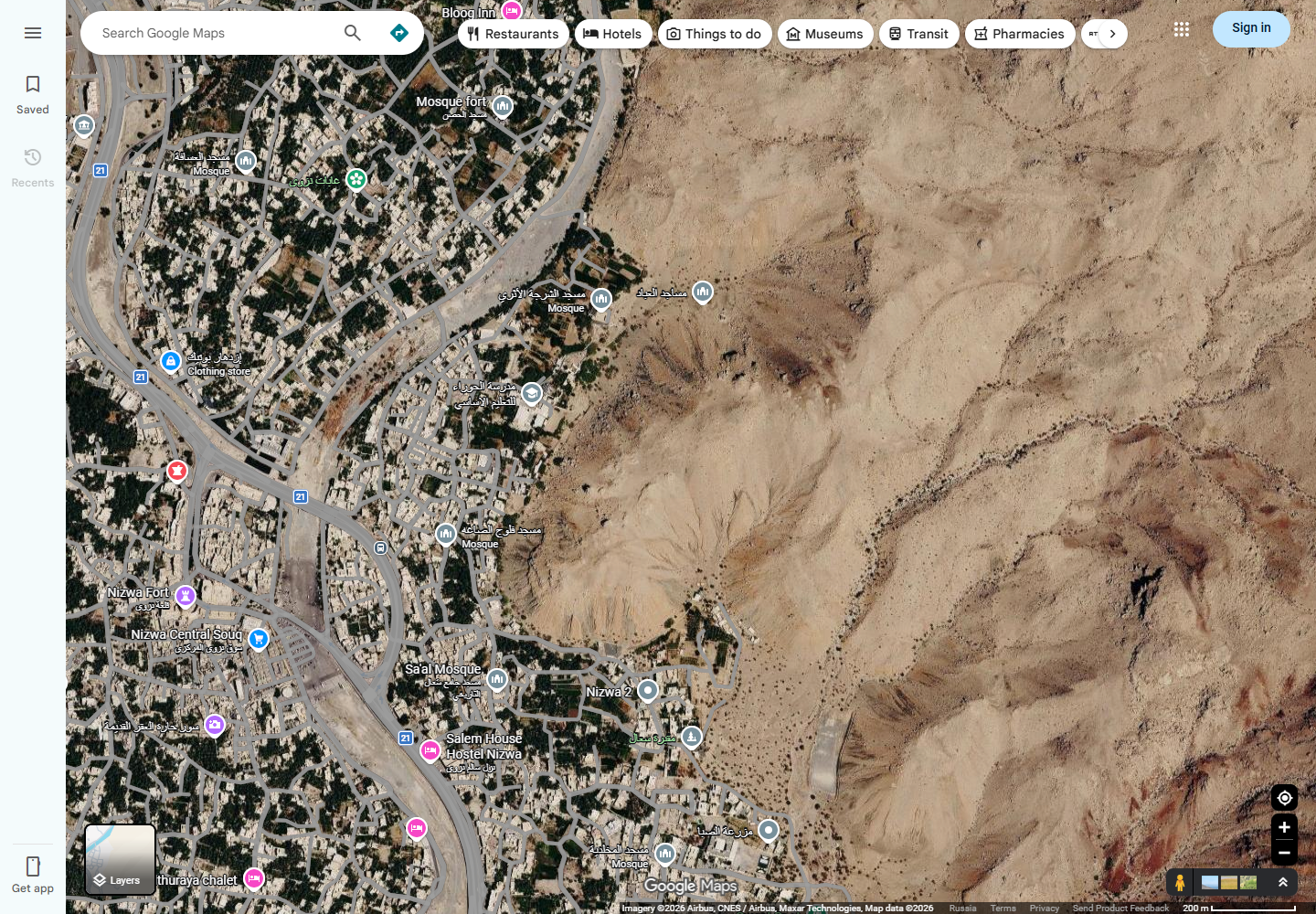
Google Maps: سياق الموقع بواجهة إنجليزية. حقوق الصور للموردين الظاهرين؛ لقطة 12 أكتوبر 2026 وليست رفعاً مساحياً.
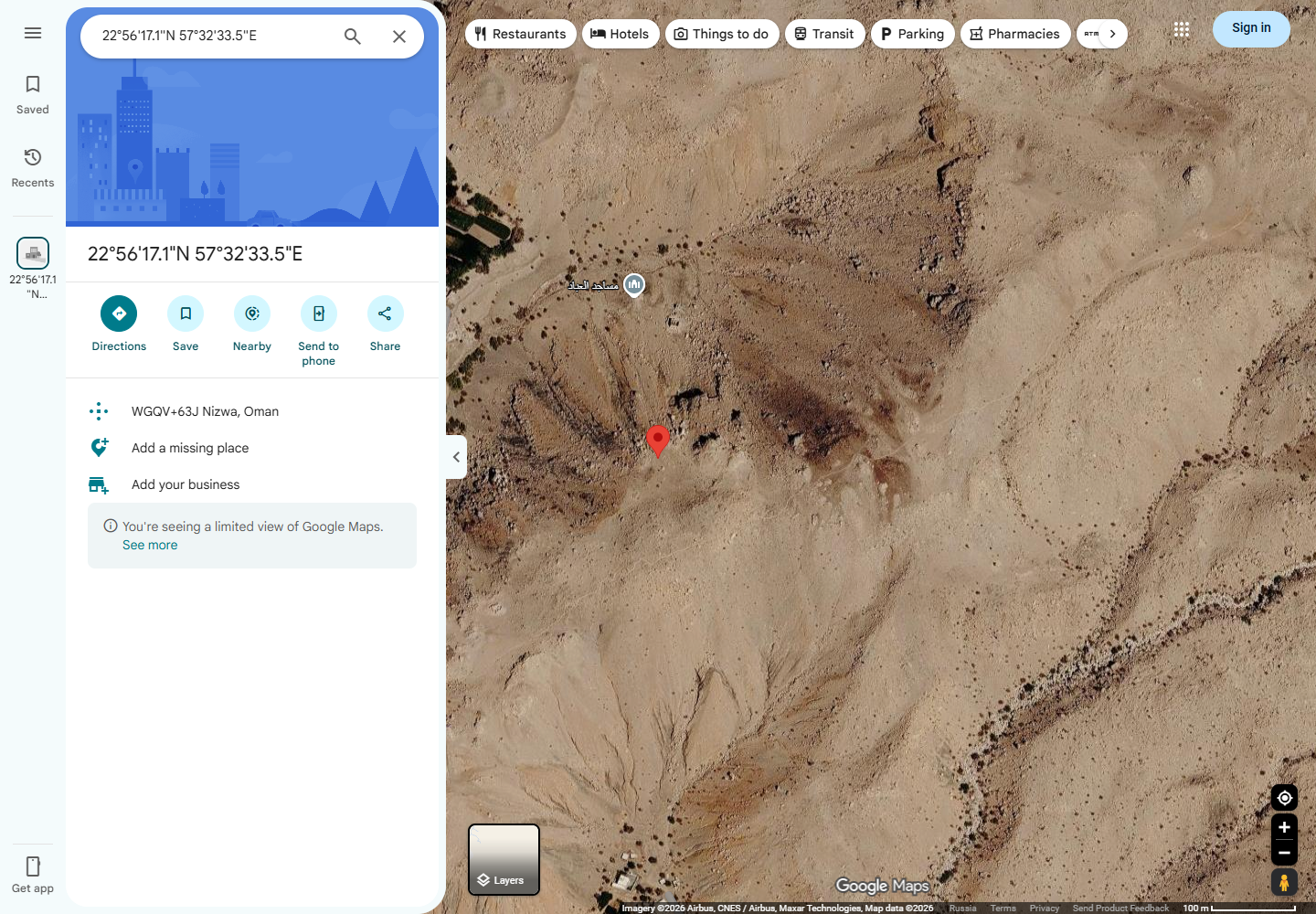
Google Maps: مؤشر العجلة المقترح بواجهة إنجليزية. حقوق الصور للموردين الظاهرين؛ لقطة 12 أكتوبر 2026.

نطاق التغطية ومطابقة المصادر

توجيه العميل بتاريخ 12 أكتوبر 2026: يُعتمد محيط العميل في “Measured Area (1).kml” ‏(KML 2) نطاقاً أساسياً للمسح، بمساحة نحو 31.53 هكتار. المحيط البرتقالي المعدل وKML الأول مراجع سياقية فقط ولا يعيدان تحديد نطاق المسح. الشريط الخارجي بعرض 50 م اختياري ويتطلب اتفاقاً وتصريحاً منفصلين. يُؤكد الضبط المساحي والمرجع الرأسي وتصاريح التشغيل قبل الطيران. هذا اعتماد لنطاق المسح وليس إثباتاً للملكية.
  • KML الأول — مرجع الفندق: ‏“Measured Area.kml”، أربع نقاط، بمساحة تقريبية 96,796 م² / 9.68 هكتار. مرجع مرفق وليس حدوداً عقارية مثبتة.
  • KML الثاني — محيط المسح المعتمد من العميل: ‏“Measured Area (1).kml”، 18 نقطة، بمساحة تقريبية 315,295 م² / 31.53 هكتار. يحتوي على موقع العجلة المقترح.
  • مرجع العجلة W: خط العرض 22.93807942265588 وخط الطول 57.54263192669975 ‏(WGS 84). يقع في شمال KML الثاني وعلى بعد نحو 113 م خارج KML الأول. هو مؤشر موقع وليس نقطة أساس مرفوعة مساحياً. يُمسح كامل محيط العميل؛ ولا يلزم تحديد حدود تطوير شمالية مستقلة لبدء هذا المسح.

أساس التسعير: مسح كامل KML الثاني، مع عناية بموقع العجلة الشمالي والربط بمرجع الفندق. يُعرض شريط سياقي اختياري بعرض 50 م خارج KML الثاني، باتفاق منفصل مع العميل وإذن الوصول والطيران، ليبلغ الإجمالي نحو 43.82 هكتار شاملاً النطاق الأساسي. لا يُضاف تلقائياً إلى النطاق الأساسي. تُسعَّر امتدادات الطرق والمرافق والتصريف الإضافية منفصلة، ويُتتبَّع التصريف خارج الشريط عند طلب المصمم.

حُسبت مساحات KML باستخدام WGS 84 / UTM 40N. يحتوي ملفا KML على خطوط مغلقة وعلامات نقاط بارتفاعات صفرية. هذه الأصفار ليست مناسيب أرض مقاسة.

الإحداثيات المعدلة — المحيط البرتقالي

الإحداثيات المعدلة المعروضة باللون البرتقالي مرجع سياقي، وليست حدود ملكية معتمدة. يبقى KML الثاني محيط المسح الأساسي. المرجع الأفقي للإحداثيات أدناه WGS 84 بالدرجات؛ لا توجد مناسيب أرض مقاسة.

PointLongitude (°)Latitude (°)
P157.541202938422.9369639851
P257.542190616022.9366317313
P357.540657641922.9335327092
P457.538982759622.9336487649
P557.539642904322.9353779023
P657.540544010822.9365853044
تنزيل الإحداثيات المعدلة CSV

مرجع الإحداثيات والمناسيب

  • الاتفاق مع المسّاح المسؤول والمصمم على المرجع الأفقي وتحقيقه وحقبته والإسقاط والوحدات والتحويل. تُحفظ الإحداثيات البلدية الأصلية. شبكة العمل المقترحة: WGS 84 / UTM zone 40N، الرمز EPSG:32640، بالمتر، بعد الاتفاق فقط؛ مع WKT2 وتفاصيل التحويل. تُسلَّم الشبكة المحلية الرسمية أيضاً عند طلبها مع اختبارات مستقلة للتحويل.
  • ربط المناسيب الأرثومترية بروبير محلي معتمد ونظام رأسي ونموذج جيويد مسمّيين. يُذكر رقم الروبير ومنسوبه المنشور والطريقة وعدم اليقين. لا تُسمى ارتفاعات GNSS الإهليلجية مناسيب فوق متوسط سطح البحر. تُسجَّل h وفاصل الجيويد N والمنسوب H = h − N عند انطباقه.
  • إذا تعذر الربط الرأسي المعتمد، يُتفق على مرجع محلي مؤقت ويُوسم قبل العمل. لا يُقبل كمناسيب مطلقة رسمية حتى إتمام الربط. تُحفظ أرصاد GNSS الخام لإعادة المعالجة.
  • إنشاء روبيرين دائمين على الأقل خارج الأعمال الترابية المستقبلية، مع الإحداثيات والمناسيب والصور ورسومات الوصول. يُتحقق من الربط الرأسي بميزانية مغلقة أو بطريقة مستقلة أخرى مبررة.

أهداف الالتقاط ومعايير القبول

البندمتطلب المشروع
الدقة المطلقةالخطأ الأفقي RMSE ≤ 0.05 م على أهداف تحقق واضحة؛ والخطأ الرأسي RMSE ≤ 0.05 م على نقاط مستقلة بأرض مكشوفة وثابتة. تُعرض انحيازات X/Y/Z وRMSE وأقصى خطأ وكل فرق. يُحقق في الفروق الرأسية المطلقة > 0.10 م وتُصحح أو يُعتمد كل استثناء صراحةً مع توثيقه.
الضبط والتحققخمسة أهداف ضبط موزعة على الأقل، منفصلة عن 30 نقطة تحقق مستقلة على الأقل تغطي الشمال وحواف النطاق ومدى الارتفاعات. تضاف خمس نقاط نباتية على الأقل حيث توجد نباتات وتُعرض منفصلة. لا تُستخدم نقاط التحقق في الضبط. عدم اليقين المستهدف لمسحها ≤ 0.02 م أفقياً و≤ 0.015 م رأسياً، مع توثيق طريقة تحقيقه.
كثافة LiDARكثافة إجمالية ≥ 100 نقطة صالحة/م²، وأرض مصنفة ≥ 20 نقطة/م² على الأرض المكشوفة، بخلايا 1 م على ≥ 95% من مساحة الأرض المؤهلة. تُسلَّم خرائط الكثافة وإحصاءات المسار الواحد والاستثناءات. لا فجوات غير مفسرة بعرض يزيد على 1 م في الأرض المكشوفة. للمياه والنباتات والحجب أقنعة ثقة واستكمال أرضي عند الحاجة.
توافق المساراتعدم تطابق رأسي RMS ≤ 0.03 م على أسطح التداخل الملساء والثابتة بعد المعايرة والضبط. تُرفق المسارات المتقاطعة والرسوم؛ ولا يُخفى الاختلاف بالتنعيم.
صور RGBحجم البكسل الأرضي GSD ≤ 0.03 م؛ تداخل أمامي ≥ 85% وجانبي ≥ 80%. صور حادة بتعريض متوازن وتصحيح تشوه الغالق. تُضاف صور مائلة آمنة للمنحدرات والمنشآت ذات الصلة بالنموذج ثلاثي الأبعاد.
التضاريسشبكة DTM وDSM بحجم 0.25 م؛ كنتور كل 0.50 م وخط رئيسي كل 2.50 م. دقة الشبكة ليست الدقة المساحية. تُستخدم خطوط انكسار مقاسة؛ ولا يُختلق كنتور عبر المياه أو الفجوات غير المدعومة.
تصميم الطيراندراسة منسوب أرثومتري ثابت لكل الكتل: أعلى أرض متحقق منها مع الخلو المحسوب Hc. مسافة 60 م مرشح اختبار فقط. فحص أدنى خلو وأكبر AGL وGSD والارتفاع المسموح وكثافة LiDAR وزاوية المسح ومعدل النبضات وتداخل الشرائط (مقترح ≥ 50%) والبطاريات والمسارات المتقاطعة وفق المستشعر الفعلي. راجع تكتيك التصوير.

هذه أهداف تعاقدية وليست ادعاءً باعتماد ASPRS. يُشار في تقرير الاختبار إلى الإصدار الثاني، النسخة الثانية (2024)، مع عدم يقين مسح نقاط التحقق. تتطلب المطابقة الرسمية إثبات جميع المتطلبات المنطبقة. تُعرض أخطاء الأرض تحت النباتات منفصلة ولا تُعمَّم دقة الأرض المكشوفة على التضاريس المحجوبة.

تكتيك التصوير وربط الكتل
منسوب ثابت هو الخيار الأساسي للدراسة. مسافة 60 م فوق أعلى أرض مرشح اختبار فقط؛ يُحسب الارتفاع النهائي وفق التضاريس والعوائق والتصاريح وGSD وكثافة LiDAR.
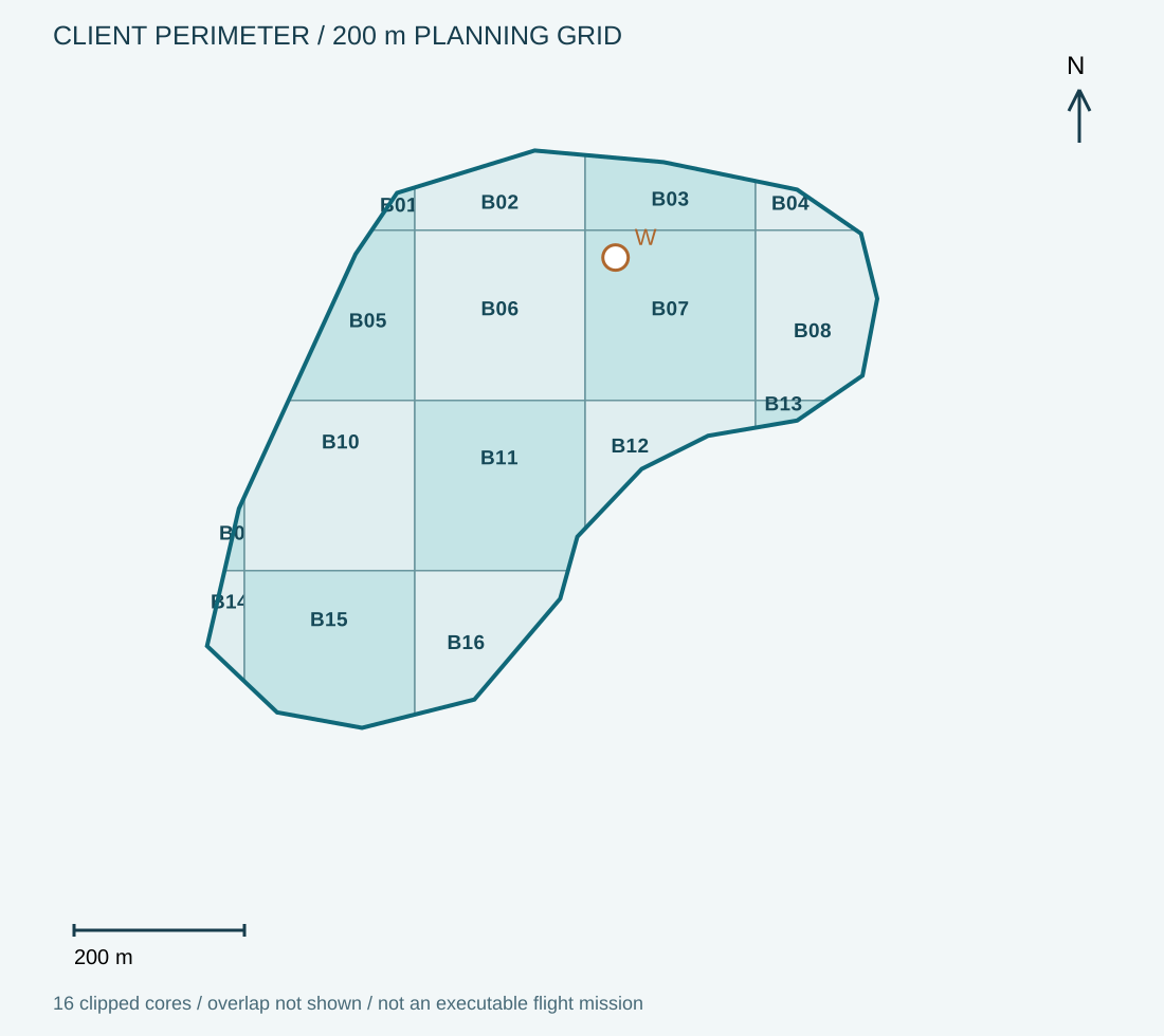
شبكة تخطيط 200 م داخل محيط العميل
من KML العميل؛ التداخل غير مرسوم؛ الأرقام لا تحدد ترتيب الطيران.

بطاقة اختبار أولية

منسوب الطيران
Zmax + Hc
Hc مرشح اختبار
60 m
ميل كاميرا RGB
−90° / nadir
تداخل RGB
85% / 80%
سرعة الاختبار
4 m/s
شبكة الخلايا
200 × 200 m

إعدادات أولية وليست مهمة معتمدة.

GeoJSON ↓ · CSV ↓
  1. 16 خلية داخل محيط العميل

    تُستخدم خلايا التخطيط المقصوصة 200 × 200 م من B01 إلى B16، بمجموع 31.53 هكتار. يمكن ضم الأجزاء الصغيرة إلى طلعات مجاورة. هي خلايا تنظيمية وليست خرائط مستقلة أو 16 رحلة إلزامية. يحدد الطيار مواقع الإقلاع وتجميع الطلعات بعد المعاينة.

  2. منسوب طيران موحد

    الاستراتيجية الأولية المفضلة هي منسوب طيران أرثومتري ثابت عبر النطاق مع كاميرا RGB رأسية إلى الأسفل. لا يُعاد ضبط الارتفاع نسبةً إلى كل نقطة إقلاع جديدة. يُستخدم المرجع الرأسي نفسه مع التحويل الصحيح إلى نمط الارتفاع في برنامج المهمة. المنسوب الثابت لا يزيل إزاحة التضاريس من الصور الخام؛ يلزم الضبط الفوتوغرامتري المشترك والتصحيح التعامدي.

  3. اختيار الارتفاع بالحساب، وليس تثبيت 80 م

    تُدرس مسافة 60 م فوق أعلى نقطة أرض متحقق منها كمرشح اختبار أولي وليست إعداداً معتمداً. Zmax وZmin هما أعلى وأدنى منسوب أرض، وHc الخلو فوق Zmax. منسوب الطيران = Zmax + Hc؛ ويتغير AGL من Hc إلى Hc + (Zmax − Zmin). تُفحص ارتفاعات العوائق وخلو السلامة منفصلة، بما فيها الأسلاك والأعمدة والأشجار. يحدد الطيار والمسّاح Hc بعد معرفة التضاريس وحدود المستشعر والارتفاع المسموح.

  4. فحص أدنى وأعلى أرض

    لعدسة ثابتة: GSD = AGL × عرض المستشعر ÷ (البعد البؤري × عرض الصورة بالبكسل). أدنى أرض لها أكبر AGL وأسوأ GSD؛ ويجب تحقيق ≤ 3 سم/بكسل هناك. أعلى أرض لها أصغر بصمة تصوير؛ وتُحسب عندها مسافات الخطوط وتشغيل الكاميرا لضمان التداخل. تُفحص كثافة LiDAR عند أكبر مدى وزاوية المسح الفعلية. إذا تعذر تحقيق المتطلبات بمنسوب ثابت وآمن، يُقترح مستشعر آخر أو تقارب الخطوط وخفض السرعة حيث يفيد أو نطاقات ارتفاع متفق عليها منفصلة؛ ولا تُقبل جودة أقل دون اتفاق.

  5. مثال رقمي — ليس الكاميرا المركبة

    مثال: مستشعر 13.2 × 8.8 مم وعدسة 8.8 مم وصورة 5472 × 3648 بكسل. عند AGL قدره 60 م تكون البصمة 90 × 60 م وGSD نحو 1.64 سم/بكسل. مع فرق تضاريس 30 م يصبح AGL عند أدنى أرض 90 م وGSD نحو 2.47 سم/بكسل. حد AGL لتحقيق 3 سم/بكسل في هذا المثال 109.44 م؛ لذلك يجب ألا يتجاوز Hc مع فرق التضاريس 109.44 م. تُستبدل هذه القيم بالكاميرا الفعلية والتضاريس المقاسة.

  6. كاميرا رأسية وإعداد ثابت

    محور RGB: ‏90° تحت الأفق / الحامل −90° / انحراف 0° عن الشاقول المحلي، وليس العمود على المنحدر. سماحية الجودة المقترحة ≤ 3° للصور المقبولة في الخطوط المستقيمة؛ تُفحص الوضعية وتُستبعد الانعطافات والتسارع وتُعاد الفجوات. تثبيت الكاميرا والعدسة والبعد البؤري والاتجاه والتركيز المتحقق منه وتوازن الأبيض، دون تقريب أو تأطير آلي. سمت الشبكة واحد، مبدئياً شمال–جنوب، مع السماح بالعودة المعاكسة 180°. تُوسم مسارات التحقق شرق–غرب منفصلة.

  7. التداخل وتغيير البطارية

    يمتد الالتقاط 50 م داخل كل خلية مجاورة، أي شريط مشترك يقارب 100 م حيث أمكن. يُزاد ليشمل مسارين كاملين وبصمتَي صورة طولياً. يستمر التصوير عبر حدود الخلايا. بعد تبديل البطارية يُعاد مساران كاملان وطول بصمتَي صورة. التغطية خارج المحيط تحتاج إلى تصريح؛ والشريط الخارجي 50 م خيار منفصل.

  8. التداخل والسرعة والتعريض

    تداخل RGB أمامي ≥ 85% وجانبي ≥ 80%. للبصمة الدنيا 90 × 60 م في المثال، مع 90 م عرضياً: تباعد الخطوط 18 م، ومسافة التصوير 9 م، والفاصل 2.25 ثانية عند سرعة اختبار 4 م/ث. تُفحص حدود تشغيل الكاميرا والكثافة والطمس. يُختبر تعريض 1/1000 ثانية حيث تسمح الإضاءة، مع طمس حركة ≤ 0.5 بكسل. لا تُحتسب صور الانعطاف ضمن التداخل. تُصور الخلايا المجاورة بإضاءة وطقس متقاربين.

  9. LiDAR والصور الإضافية

    النظر الرأسي لكاميرا RGB لا يعني أن جميع أشعة الليزر رأسية. تُستخدم هندسة الماسح المعايرة وإعدادات المصنع. تُنفذ رحلة RGB مستقلة إذا تعذر استيفاء المتطلبات بالمستشعر المشترك. تُلتقط الصور المائلة كمجموعة منفصلة موسومة للمنشآت والنموذج، مع تغطية رأسية كاملة للأورثوموزايك.

  10. ناتج موحد مضبوط

    استخدام شبكة ضبط ومرجع واحد وضبط حزمة مشترك بنقاط ربط الصور، وضبط شرائط LiDAR وحجب نقاط التحقق المستقلة. لا تُحرك منتجات الخلايا أو تُغير مقاييسها بالعين. يُسلم DTM وأورثوموزايك متصلان، وتُعرض فجوات الوصلات والحواف المزدوجة ودرجات الارتفاع وفروقها وفق معايير القبول.
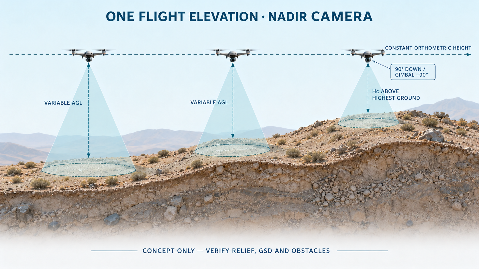
منسوب ثابت وكاميرا رأسية؛ توضيح مولد
رسم مولد، ليس تضاريس الموقع ولا بمقياس. Hc يُحدد بالحساب.

مراجع: PIX4D — terrain variation · PIX4D — acquisition planning. توصي PIX4D بتتبع التضاريس لتثبيت GSD؛ هنا يُدرس المنسوب الثابت حسب تفضيل العميل مع فحص أسوأ الحالات. الأرقام خيارات للمشروع وليست إعدادات مصنع.

خطوات العمل للمشغّل

  1. تثبيت حزمة الموقع

    تنزيل الأصول واعتماد محيط KML الثاني المحدد من العميل كنطاق أساسي، وتوثيق أي شريط إضافي متفق عليه بصورة منفصلة. تأكيد شبكة المسح والمرجع الرأسي. تحويل خطوط KML المغلقة إلى مضلعات GIS سليمة دون تغيير الإحداثيات الأصلية. التأكد من احتواء التغطية على مؤشر العجلة.

  2. استكمال التصاريح والمعاينة

    يحصل المشغّل المرخص على موافقات هيئة الطيران المدني الحالية والتصاريح المنطبقة للمسح والتصوير والوصول. تُراجع قيود المجال الجوي وNOTAM ونطاق التشغيل بما فيه الشريط المحيط. تُعاين الطرق والأسلاك والأشخاص والحيوانات والمنحدرات والمعالم التراثية ومواقع الهبوط البديلة مع العميل. تُحدد مناطق العزل وخط الرؤية والمراقبون والطوارئ والتأمين.

  3. إنشاء ضبط مستقل

    تركيب الروبيرات والأهداف ورصد GNSS بربط موثق بمحطة قاعدة أو CORS، وحفظ RINEX والسجلات وارتفاعات الهوائيات. استخدام الميزانية أو المحطة الشاملة عند حجب GNSS. قياس نقاط التحقق قبل الضبط وحجبها عن معالجة الإنتاج. تصوير جميع النقاط وتوثيقها.

  4. اعتماد مهمة تراعي التضاريس

    استخدام نموذج أولي ومعاينة العوائق لحساب منسوب طيران آمن موحد وفحص AGL المتغير؛ ولا تُعامل التضاريس التقريبية كمناسيب تصميم مقاسة. حساب التغطية عند أعلى وأدنى أرض والتداخل والانعطافات المسموحة والمسارات المتقاطعة. فحص الخلو من العوائق وارتفاع العودة وإجراء انقطاع الاتصال واحتياطي البطارية وحدود المصنع. يسجل الطيار حدود الطقس والإيقاف الآمنة؛ ولا يُقلع عند الغبار أو المطر أو ضعف الرؤية أو الرياح غير المناسبة.

  5. تنفيذ مسار معايرة أولاً

    فحص معايرة المستشعر وأذرع الإزاحة ومحاور التركيب وتزامن GNSS/IMU وإعدادات الكاميرا. تنفيذ مسار قصير وآخر متقاطع فوق الضبط. فحص عينة معالجة سريعاً لجودة المسار والكثافة والتطابق وحدّة الصور قبل الالتقاط الكامل.

  6. التقاط LiDAR وRGB

    الطيران وفق الشبكة المعتمدة بمنسوب موحد متفق عليه وسرعة متسقة، والتقاط المسارات المتقاطعة والصور المائلة المطلوبة. تجنب الأشخاص غير المحميين والأملاك غير المصرح بها. مراقبة GNSS والتخزين والبطاريات؛ وإيقاف المهمة وتوثيق الخلل. تضمين مداخل العجلة الشمالية وروابط التصريف.

  7. فحص الاكتمال قبل المغادرة

    فحص المسارات والتغطية وأعداد الملفات الخام والضبابية والكثافة والأهداف والفجوات في اليوم نفسه. إعادة المناطق غير المطابقة ضمن صلاحية التصاريح. رفع خطوط الانكسار الحرجة المحجوبة وقيعان العبارات وروابط الطرق أرضياً. وسم المعالم المتعذر الوصول إليها وتصويرها.

  8. المعالجة والتحقق والتسليم

    نسخ الخام إلى وسيطين منفصلين. تصحيح المسارات بـ PPK/RTK ومعايرة المحاور وضبط الشرائط والتصنيف، ثم مراجعة الأرض يدوياً قرب الجدران والمنحدرات والنباتات. إنشاء التضاريس والأورثوموزايك والنموذج. الاختبار بالنقاط المحجوبة وتصحيح الإخفاقات أو الإفصاح عنها، وتسليم البيانات القابلة للتحرير وتقرير الجودة الموقع للحصول على قبول المصمم.

المعالم الأرضية وحدود المسح

رفع قمم المنحدرات وأقدامها والنتوءات الصخرية والجدران الساندة والأسوار والمباني والبوابات وحواف الطرق ومناسيبها والممرات والأسلاك والأعمدة وأغطية المرافق الظاهرة والجذوع والتيجان وقنوات التصريف. رفع خطوط الانكسار ثلاثية الأبعاد واتجاهات الجريان وقيعان مداخل العبارات ومخارجها والروابط ذات الصلة. تقديم مناسيب نقطية بشبكة 5 م في منطقة الأولوية الشمالية، و10 م في غيرها، وعند جميع تغيّرات الميل والمعالم الحرجة.

لا يحدد LiDAR المرافق تحت الأرض أو الأرض أسفل المنشآت المعتمة أو تحمل التربة أو مناسيب الفيضان التصميمية. يُطلب كشف المرافق والرفع الأرضي للمعالم المحجوبة والدراسة الجيوتقنية والنمذجة الهيدرولوجية بصورة مستقلة. لا تُختلق المناسيب المفقودة ولا يُستخدم مؤشر العجلة للتوقيع الإنشائي.

التسليم إلى فريق المخطط العام

  • 01 · الضبط المساحيتقرير موقع؛ CSV للنقاط (المعرف وE وN وH وh عند توفره والرمز والطريقة وعدم اليقين)، وصور الروبيرات ورسوماتها وسجلات RINEX والقاعدة والجهاز المتحرك والمرجع والحقبة والجيويد وWKT2.
  • 02 · السحابة النقطيةLAS 1.4 / LAZ دون ترقيق مع تصنيف الأرض والنباتات والمباني والضوضاء وفئات ASPRS المنطبقة؛ ورقم العودة والشدة ووقت GPS ومعرفات المصدر والرحلة وRGB حيث يتوفر. تُرفق بيانات المستشعر الخام والمسارات ومشروع المعالجة وإعداداته.
  • 03 · التضاريس والصورDTM وDSM بصيغة GeoTIFF وشبكة 0.25 م، وأورثوموزايك GeoTIFF ≤ 0.03 م، وتظليل وميل بالدرجات وكنتور 0.50 م وأقنعة المياه والفجوات وضعف الثقة. تُحفظ NoData وبيانات المرجع.
  • 04 · قاعدة تصميم قابلة للتحريرDWG وDXF بطبقات منظمة لخطوط الانكسار ثلاثية الأبعاد والكنتور والمناسيب والمعالم؛ وTIN بصيغة LandXML؛ وGeoPackage وحدود GeoJSON/KML. تُذكر الوحدات والمرجع وتُطابق الطبقات دون إزاحات يدوية.
  • 05 · النموذج السياقي ثلاثي الأبعادOBJ مع MTL والصور النسيجية، ومعاينة GLB خفيفة. يُرفق تحويل الإسناد والأصل المحلي واتجاه المحاور والمقياس وثلاث نقاط تحقق على الأقل تربط النموذج بالإحداثيات المساحية. الشبكة لا تحل محل DTM للأرض.
  • 06 · الجودة والأدلة الميدانيةCSV لفروق نقاط التحقق وحسابات الدقة وخرائط الكثافة والتداخل وإحصاءات الشرائط وسجلات الطيران والفجوات والاستثناءات ومخطط مسح PDF مشروح بمقياس 1:500 أو 1:1,000 حسب الحاجة وصور ميدانية مؤرخة.

تُنظم الحزمة في Raw / Control / PointCloud / Terrain / Imagery / CAD-GIS / Model / QA، مع README وإصدارات البرامج وسجل المعالجة وقائمة SHA-256. يفتح المصمم عينات DWG/LandXML وGeoTIFF وLAZ والنموذج ويتحقق من تطابقها على نقاط التحقق نفسها. تُحفظ البيانات الخام 12 شهراً على الأقل بعد القبول وفق اتفاقية التعامل مع البيانات.

شروط الانتقال وعرض السعر

قبل الطيران: تسجيل KML الثاني كنطاق أساسي محدد من العميل وأي شريط إضافي متفق عليه منفصلاً؛ والاتفاق على شبكة المسح والضبط الرأسي؛ وتقديم التصاريح والمخاطر وخطة الطيران والمعدات والمعايرة وخطة الضبط. مطابقة القطعة البلدية مطلوبة فقط لمهمة عقارية أو قانونية لاحقة، وليست شرطاً لمسح محيط العميل.

قبل مغادرة الموقع: اكتمال النسخ والتغطية والاستكمال الأرضي وفحوص المعايرة ومعالجة النقص.

قبل القبول: اجتياز الدقة والاكتمال واعتماد الاستثناءات وفتح الملفات وتطابقها وتسليم تقارير الجودة والضبط الموقعة. يصحح المقاول الإخفاقات المنسوبة إليه ويعيد التسليم دون تكلفة إضافية وفق العقد.

يُسعَّر KML الثاني وشريط 50 م منفصلين، مع خيارات الممرات والاستكمال الأرضي. يُذكر نوع الطائرة والمستشعر والكاميرا والمعايرة والمسّاح والطيار المسؤولان والتصاريح وشبكة الضبط والتحقق والدقة الممكنة وبرامج المعالجة ومتطلبات التعبئة والجدول المقترح من الاعتماد والأسعار والاستثناءات. لا يوجد تاريخ بدء أو تصريح ضمني.

ملفات ومصادر

ملفات الحدود للمراجعة فقط، وليست ملفات ملاحة أو مسارات طيران. بيانات الارتفاع الفعلية ستنتج عن المسح.

تمت مراجعة المصادر والواجهة في 12 أكتوبر 2026. يُعاد التحقق من التصاريح والقيود وقت التنفيذ. الدليل مواصفات مشروع مقترحة ولا يمنح إذناً للطيران.

النتيجة المتوقعة وسجل التسليم

حزمة متصلة ذات مرجع مساحي موحد للمصمم: سحابة نقاط مصنفة وDTM للأرض وDSM وكنتور ومناسيب نقطية وأورثوموزايك ونموذج ثلاثي الأبعاد مكسو. تتطابق المراجع الأفقية والرأسية وتقارير التحقق المستقل لجميع المنتجات.
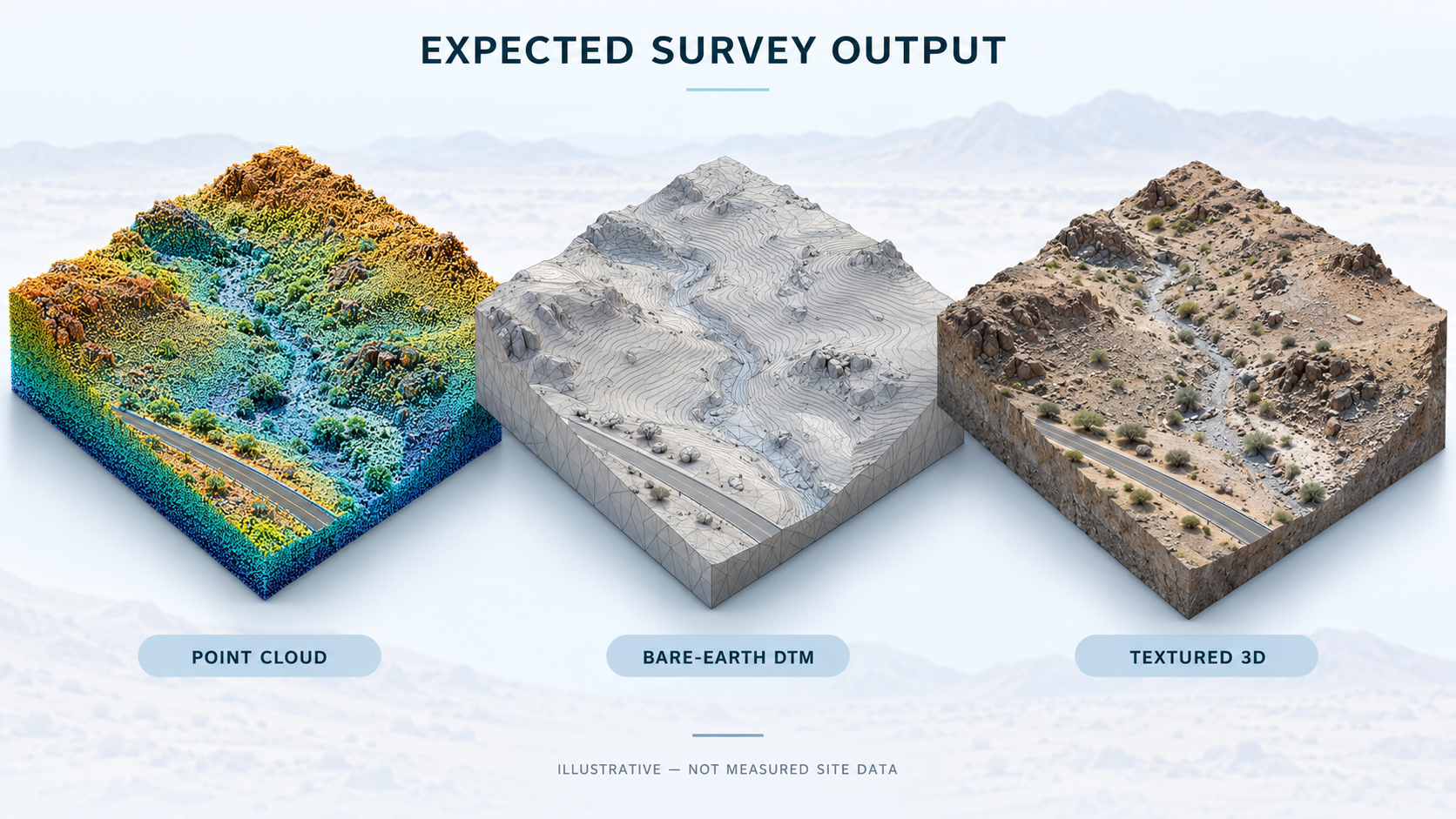
مثال مولد: سحابة نقاط وتضاريس ونموذج مكسو
مثال بصري مولد فقط. لا يمثل تضاريس نزوى المقاسة ولا تصميماً مقترحاً للبناء.

استكشف شكل التسليم ثلاثي الأبعاد

محيط العميل الأفقي الفعلي مع ارتفاعات اصطناعية توضيحية. لم تُقَس مناسيب الموقع بعد. لا تُستخدم هذه المعاينة لحساب الكميات أو التصريف أو توقيع المنشآت.

جارٍ تحميل المثال…

نموذج إكمال بيانات المقاول

يُملأ بعد المعالجة وفحص الجودة. الخانة الفارغة تعني عدم الإبلاغ وليست صفراً. ينشئ التصدير ملف JSON على جهازك؛ لا يرسل الموقع البيانات ولا يحفظها. تعبئة النموذج وحدها لا تثبت القبول.

الملفات المستلمة فعلياً

Oman / Nizwa / Revision 1.3

The ground first.
Then the master plan.

UAV LiDAR and 3D mapping specification for the proposed observation wheel site.

Operator field sequence

For quotation and coordination • Client perimeter adopted • Confirm survey control before flight

Client and adapted reference boundaries with wheel pin W
W · proposed location, not a setting-out point

Survey purpose

Acquire a georeferenced UAV LiDAR and RGB survey for the master plan of a proposed observation wheel and associated development in Nizwa, Oman. Deliver a bare-earth terrain model, elevations, contours, orthophotography and a textured 3D context model for access, drainage and initial earthworks studies.

Procurement and fieldwork specification • Revision 1.3 • 12 October 2026. Numerical targets are proposed project requirements for contractor pricing and acceptance, not measurements already achieved. No wheel foundation centre, diameter, finished floor level or development entitlement is established here.

Site maps and references

North-up diagram calculated from the files; not a height map or approved boundary. W is the wheel pin. Background grid: 100 m.

Client perimeter · KML 2 · 31.53 ha

KML 1 · 9.68 ha

P1–P6 · adapted context perimeter

Optional 50 m context buffer

KML 2 controls the survey extent. The orange adapted plot is context only and does not redefine the client perimeter.

Google Maps: site context, English interface. Imagery credited to providers shown; captured 12 October 2026, not a survey.
Google Maps: proposed wheel pin, English interface. Imagery credited to providers shown; captured 12 October 2026.

Coverage and source reconciliation

Client instruction, 12 October 2026: use the client’s perimeter in “Measured Area (1).kml” (KML 2) as the controlling survey extent, approximately 31.53 ha. The adapted orange plot and KML 1 are context only and do not redefine this survey extent. The 50 m external buffer is optional and requires separate agreement and permission. Confirm survey control, height datum and operational permissions before flight. This defines survey scope, not legal ownership.
  • KML 1 — hotel reference: “Measured Area.kml”, 4 vertices, approximately 96,796 m² / 9.68 ha. A supplied reference, not a verified cadastral polygon.
  • KML 2 — client-selected survey perimeter: “Measured Area (1).kml”, 18 vertices, approximately 315,295 m² / 31.53 ha. Contains the proposed wheel location.
  • Wheel reference W: latitude 22.93807942265588, longitude 57.54263192669975 (WGS 84). It is in northern KML 2, about 113 m outside KML 1. This is a location pin, not a surveyed foundation point. The whole client perimeter is to be surveyed; a separate northern development boundary is not needed to start this survey.

Base quotation: survey all of KML 2, paying particular attention to the northern wheel location and hotel interfaces. Offer an optional 50 m context buffer outside KML 2, subject to separate client agreement and access/flight permission: approximately 43.82 ha including the base area. Do not add it to the base scope automatically. Price additional road, utility and drainage corridors separately; follow drainage beyond the buffer where the designer requires it.

KML areas calculated in WGS 84 / UTM 40N. Both KMLs contain closed LineStrings and point markers with zero altitude. These zeros are not surveyed ground elevations.

Adapted coordinates — orange perimeter

The adapted orange coordinates are a context reference, not approved cadastral boundaries. KML 2 remains the controlling survey perimeter. Coordinates below use WGS 84 in decimal degrees; no measured ground heights are provided.

PointLongitude (°)Latitude (°)
P157.541202938422.9369639851
P257.542190616022.9366317313
P357.540657641922.9335327092
P457.538982759622.9336487649
P557.539642904322.9353779023
P657.540544010822.9365853044
Download adapted coordinates CSV

Coordinate reference and heights

  • Agree horizontal datum, realization/epoch, projection, units and transformation with the responsible surveyor and master-plan designer; involve the municipality if an official local-grid deliverable is requested. Preserve source municipal coordinates. Proposed working grid: WGS 84 / UTM zone 40N, EPSG:32640, metres, only after agreement; provide WKT2 and transformation details. Also supply the official local grid if required, with independent transformation checks.
  • Tie orthometric heights to an accepted local benchmark and named vertical datum/geoid model. State benchmark ID, published level, method and uncertainty. Never label GNSS ellipsoidal heights as mean sea level. Record h, geoid separation N and H = h − N where applicable.
  • If an approved vertical tie is unavailable, agree and label a temporary local datum before work. Do not accept it as official absolute elevations until the tie is resolved. Retain raw GNSS for reprocessing.
  • Establish at least two durable site benchmarks outside future earthworks, with coordinates, levels, photographs and recovery sketches. Verify the vertical tie by closed levelling or another justified independent method.

Acquisition and acceptance targets

ItemProject requirement
Absolute accuracyHorizontal RMSE ≤ 0.05 m on identifiable check targets; vertical RMSE ≤ 0.05 m on independent, open, stable ground checkpoints. Report X/Y/Z bias, RMSE, maximum error and every residual. Investigate absolute Z residuals > 0.10 m; correct or obtain explicit documented acceptance of each exception.
Control and checksAt least 5 distributed control targets, separate from at least 30 independent checkpoints covering the northern focus, AOI edges and elevation range. Add at least 5 vegetated checks where vegetation exists; report separately. Never use checks for adjustment. Target surveyed control/check uncertainty ≤ 0.02 m horizontal and ≤ 0.015 m vertical; document how achieved.
LiDAR sampling≥ 100 valid points/m² aggregate and ≥ 20 classified ground points/m² on exposed ground, on 1 m cells over ≥ 95% of eligible land area. Supply density maps, single-swath statistics and exclusions. No unexplained gaps wider than 1 m on open ground. Water, vegetation and occlusion require confidence masks and ground infill where necessary.
Strip agreement≤ 0.03 m RMS vertical mismatch on smooth, stable overlap surfaces after calibration/adjustment. Include crossing strips and plots; do not conceal mismatch with smoothing.
RGB imageryGSD ≤ 0.03 m; forward overlap ≥ 85%, side overlap ≥ 80%. Sharp, evenly exposed images and corrected shutter distortion. Add safe oblique coverage of relevant slopes and structures for the 3D context model.
TerrainDTM and DSM at 0.25 m grid; 0.50 m contours with 2.50 m index contours. Grid resolution is not survey accuracy. Use measured breaklines; do not invent contours across water or unsupported voids.
Flight designStudy a constant orthometric flight elevation across all blocks: highest verified ground elevation + calculated clearance Hc. 60 m is a test candidate only. Verify minimum clearance and maximum AGL/GSD, permitted altitude, LiDAR density, scan angle, pulse rate, swath overlap (propose ≥ 50%), battery plan and cross-strips using the actual sensor. See Flight tactics.

These are contract targets, not an ASPRS certification claim. Reference ASPRS Edition 2, Version 2 (2024) in the test report, including checkpoint survey uncertainty. Formal compliance claims require evidence of all applicable requirements. Report vegetated-ground errors separately; do not apply bare-ground accuracy to hidden terrain.

Flight tactics and block stitching

Constant elevation is the preferred study option. 60 m above highest ground is a test candidate only; calculate final height from relief, obstacles, permits, GSD and LiDAR density.
200 m planning grid within client perimeter
From client KML; overlap not drawn; IDs do not prescribe flight order.

Preliminary test card

Flight elevation
Zmax + Hc
Hc test candidate
60 m
RGB pitch
−90° / nadir
RGB overlap
85% / 80%
Test speed
4 m/s
Core grid
200 × 200 m

Starting values, not an approved mission.

GeoJSON ↓ · CSV ↓
  1. 16 cores within your perimeter

    Use the 16 clipped 200 × 200 m planning cells B01–B16, totalling 31.53 ha. Merge tiny edge fragments into neighbouring sorties as needed. These are organisational cells, not independent maps or 16 mandatory flights. The pilot selects safe launch sites and sortie groups after reconnaissance.

  2. One common flight elevation

    Preferred starting strategy: one constant orthometric flight elevation across the AOI, with a strict nadir RGB camera. Do not reset height relative to each new take-off point. Use the same vertical reference and convert properly to the altitude mode used by the mission software. Constant altitude does not remove relief displacement from raw photographs; joint photogrammetric adjustment and orthorectification are required.

  3. Choose height by calculation, not a fixed 80 m

    Study 60 m above the highest verified ground point as an initial test candidate, not an approved setting. Let Zmax/Zmin be ground elevations and Hc the clearance above Zmax. Flight elevation = Zmax + Hc; AGL varies from Hc to Hc + (Zmax − Zmin). Check obstacle heights and safety clearance separately, including wires, poles and trees. The pilot and surveyor select Hc only after site relief, sensor limits and permitted altitude are known.

  4. Check the lowest and highest ground

    For a fixed lens, GSD = AGL × sensor width / (focal length × image width in pixels). The lowest ground has the largest AGL and worst GSD: require ≤ 3 cm/px there. The highest ground has the smallest footprint: calculate line spacing and trigger distance there to maintain overlap. Check LiDAR density at the largest range and actual scan angle. If no safe constant elevation meets both requirements, propose another camera, tighter line spacing/lower speed where effective, or separately agreed elevation bands; do not silently accept degraded data.

  5. Numerical example — not the installed camera

    Example sensor 13.2 × 8.8 mm, lens 8.8 mm, 5472 × 3648 px: at 60 m AGL the footprint is 90 × 60 m and GSD 1.64 cm/px. With 30 m relief, lowest-ground AGL becomes 90 m and GSD 2.47 cm/px. At 3 cm/px the maximum allowed AGL is 109.44 m for this example; therefore Hc + relief must not exceed 109.44 m. These values must be replaced with the actual camera and surveyed relief.

  6. Strict nadir and fixed camera

    RGB optical axis: 90° below horizontal / gimbal −90° / 0° off nadir, referenced to local vertical, not normal to a slope. Proposed QA tolerance ≤ 3° on accepted straight-run images; inspect attitude logs, exclude turns/acceleration and re-fly gaps. Keep camera, lens, focal length, orientation, verified focus and white balance consistent; no zoom or automatic framing. Use one grid azimuth across all blocks, provisionally north–south; reciprocal 180° legs are allowed. Label east–west check strips separately.

  7. Internal overlap and battery changes

    Extend acquisition 50 m into each adjacent core: approximately 100 m shared width where possible. Increase this to include at least two complete strips and two along-track footprints. Continue capturing across core edges. After a battery change repeat at least two complete lines and two footprint lengths. Outside-perimeter coverage still requires permission; the external 50 m buffer is a separate option.

  8. Overlap, speed and exposure

    RGB overlap ≥ 85% forward / ≥ 80% side. For the example 90 × 60 m minimum footprint, with 90 m across-track: line spacing 18 m, trigger distance 9 m, interval 2.25 s at a test speed of 4 m/s. Check trigger limits, density and motion blur. Test 1/1000 s exposure where light permits; require blur ≤ 0.5 pixel. Do not count turn frames for overlap. Fly adjacent blocks in comparable light/weather.

  9. LiDAR and supplemental images

    RGB nadir does not imply all laser beams are vertical. Use the scanner’s calibrated geometry and manufacturer settings. Fly a separate RGB pass if a combined payload cannot satisfy both requirements. Capture obliques in a separately labelled dataset for structures and 3D; keep full nadir coverage for the orthomosaic.

  10. One adjusted output

    Use one control network, datum and joint image bundle adjustment with shared tie points; align LiDAR strips and withhold independent checkpoints. Never shift, scale or warp block products by eye. Deliver a seamless DTM/orthomosaic and report boundary gaps, double edges, height steps and seam residuals against the acceptance targets.

Generated constant-elevation nadir-camera schematic
Generated schematic, not site relief and not to scale. Hc is selected by calculation.

References: PIX4D — terrain variation · PIX4D — acquisition planning. PIX4D recommends terrain following for consistent GSD; this client-preferred constant-elevation option requires worst-case checks. Numbers are proposed project choices, not manufacturer defaults.

Operator field sequence

  1. Resolve the site package

    Download the originals. Use the client-selected KML 2 perimeter as the base AOI; record any separately agreed buffer. Confirm the survey grid and height datum. Convert closed KML LineStrings to valid GIS polygons without changing source coordinates. Check that the wheel pin lies within coverage.

  2. Secure permissions and inspect

    The licensed operator must obtain current Oman CAA operational approvals and applicable aerial-survey, imagery and site-access permissions. Verify current airspace/NOTAM restrictions and approved envelope, including buffer. Walk the site with the client; identify roads, wires, people, animals, slopes, heritage features and alternate landing sites. Agree exclusion zones, visual line of sight, observers, emergencies and insurance.

  3. Establish independent control

    Install benchmarks and targets. Observe GNSS with a verified base/CORS tie; preserve RINEX, logs and antenna heights. Use levelling/total station where GNSS is obstructed. Measure checkpoints before adjustment and withhold them from production processing. Photograph and document all points.

  4. Approve a terrain-aware mission

    Use a preliminary terrain model and obstacle reconnaissance to calculate one safe flight elevation and check variable AGL; do not treat approximate terrain as surveyed design levels. Calculate coverage at high/low ground, overlaps, permitted turns and cross-strips. Check clearance, return-to-home altitude, lost-link response, battery reserve and manufacturer limits. Pilot records safe weather/stop limits; do not launch in dust, rain, poor visibility or unsuitable wind.

  5. Fly a calibration strip first

    Check sensor calibration, lever arms, boresight, GNSS/IMU time synchronisation and camera settings. Fly a short test plus crossing strip over control. Inspect a quick processed sample for trajectory quality, density, alignment and sharpness before full acquisition.

  6. Acquire LiDAR and RGB

    Fly the approved grid at the agreed common elevation and consistent speed; acquire cross-strips and required obliques. Avoid unprotected people and unauthorised property. Monitor GNSS, storage and batteries; abort and log anomalies. Include northern wheel access and drainage interfaces.

  7. Check completeness before leaving

    Inspect trajectories, coverage, raw file counts, blur, density, targets and gaps the same day. Re-fly failures while permits remain valid. Ground-survey hidden critical breaklines, culvert inverts and road connections. Label and photograph inaccessible features.

  8. Process, validate, deliver

    Back up raw data to two separate devices. Correct trajectories with PPK/RTK; perform boresight/strip adjustment and classification, then manually review ground near walls, slopes and vegetation. Build terrain, orthomosaic and model. Test against withheld checkpoints, correct/disclose failures, deliver editable data and signed QA, and obtain designer acceptance.

Ground features and limits

Capture terrain crests/toes, rock outcrops, retaining walls, fences, buildings, gates, road edges/levels, paths, wires/poles, visible utility covers, tree trunks/canopies and drainage channels. Survey 3D breaklines, channel flow directions, culvert inlet/outlet inverts and relevant connections. Provide spot heights on a 5 m grid in the northern priority area, 10 m elsewhere, and at all grade changes and critical features.

LiDAR cannot establish underground utilities, ground beneath opaque structures, soil bearing capacity or flood design levels. Obtain utility detection, hidden-feature ground survey, geotechnical investigation and hydrological modelling separately. Do not invent missing levels or use the wheel pin for construction setting-out.

Handover to the master-plan team

  • 01 · Survey controlSigned report; point CSV (ID, E, N, H, h if available, code, method, uncertainty), benchmark photos/sketches, RINEX/base/rover logs, datum/epoch/geoid and WKT2.
  • 02 · Point cloudUnthinned LAS 1.4 / LAZ with ground, vegetation, buildings, noise and applicable ASPRS classes; return number, intensity, GPS time, source/flight IDs and RGB where available. Include raw sensor data, trajectories, processing project and settings.
  • 03 · Terrain and imageryDTM + DSM GeoTIFF at 0.25 m, orthomosaic GeoTIFF ≤ 0.03 m, hillshade, slope in degrees, 0.50 m contours and water/void/low-confidence masks. Preserve NoData and CRS metadata.
  • 04 · Editable design baseDWG + DXF with organised layers, 3D breaklines, contours, spot heights and features; LandXML TIN; GeoPackage and boundary GeoJSON/KML. State units/datum. All layers must align without manual offsets.
  • 05 · 3D context modelTextured OBJ + MTL + textures, plus lightweight GLB. Include georeferencing transform, local origin, axis convention, scale and at least 3 check vertices linking model and survey coordinates. The mesh does not replace bare-earth DTM.
  • 06 · QA and field evidenceCheckpoint residual CSV, accuracy calculations, density/overlap maps, strip statistics, flight logs, gaps/exceptions, annotated survey plan PDF at 1:500 or 1:1,000 as appropriate, and dated field photos.

Package by Raw / Control / PointCloud / Terrain / Imagery / CAD-GIS / Model / QA. Include README, software versions, processing history and SHA-256 manifest. The designer must open representative DWG/LandXML, GeoTIFF, LAZ and model files and check alignment against the same checkpoints. Retain raw data for at least 12 months after acceptance, subject to the agreed data-handling contract.

Release gates and quotation

Before flight: record KML 2 as the client-selected base AOI and any separately agreed buffer; agree survey grid/vertical control; operator submits permissions, risk assessment, flight plan, equipment/calibration and control plan. Municipal plot reconciliation is only needed for a later cadastral/legal boundary task, not for this client-perimeter survey.

Before leaving site: backups, coverage, ground infill and calibration checks complete; missing areas addressed.

Before acceptance: accuracy/completeness pass, exceptions agreed, editable files open and align, signed QA/control reports delivered. Contractor corrects attributable failures and resubmits without extra cost, subject to the agreed contract.

Quote KML 2 and the 50 m context buffer separately, with optional corridors and ground infill. State platform/sensor/camera, calibration dates, responsible surveyor/pilot, permissions included, control/check network, achievable precision, processing tools, mobilisation dependencies, proposed schedule from approval, prices and exclusions. No start date or permit approval is implied.

Files and sources

Boundary files are for review, not navigation or flight missions. Actual elevation data will be produced by the survey.

Sources and interface checked on 12 October 2026. Recheck permissions and restrictions at execution. This brief proposes project specifications and does not authorise flight.

Expected result and handover record

One continuous, georeferenced package for the designer: classified point cloud, bare-earth DTM, DSM, contours, spot levels, orthomosaic and textured 3D model. All products must share the declared coordinate and height reference and match the independent check report.

Generated example: point cloud, terrain and textured model
Generated visual example only. It does not depict measured Nizwa relief or a proposed construction design.

Explore the delivery format in 3D

Actual client XY perimeter + synthetic demonstration heights. No site elevations have been measured. This preview must never be used for design quantities, drainage or setting-out.

Loading example…

Contractor completion form

Complete after processing and QA. Blank fields mean not reported, not zero. Export creates a JSON record on your device; no data is sent or saved by this site. Signing this form alone does not establish acceptance.

Files actually received